Optimizing Marking Power Settings with CerMark Laser Marking Materials
It is sometimes difficult to determine the best laser power and speed settings for CerMark materials. There are numerous variables that affect what settings you should use. The type of substrate, thickness of the substrate, and the substrate’s ability to conduct heat will influence the power needed to make a mark on it. For example, aluminum conducts heat much better than steel, so it will require more marking power and/or much slower speed. A thicker substrate will dissipate heat much faster than a thinner one, again meaning more power may be needed to make the mark. (See the CerMark publication “Heat Conductivity of Metals” for more information)
Every laser system has a different actual power out put. More variables come into play when you consider the laser type used. A laser’s wattage, the type of optics, the quality of the beam, the spot size, and even the software used will affect the mark quality you will achieve with a given power setting. For example, a higher power laser can deliver more energy than a lower power laser; a smaller spot size can produce a stronger spot of power. You can have 4 laser next to each other from the same supplier and they will all have variations in actual power output.
We can recommend a starting point for power and speed, but this may not be the best for your particular application. So what is the magic equation that crunches these variables into a perfect power and speed setting?
Well, in short, there is no equation that can calculate the perfect setting but there is a method that should help you quickly zone in on power and speed settings that will work. The key is to make a power/speed test grid.
Designing a Test Marking Grid

First, obtain a piece of your substrate, spray it with your marking material and focus it in your laser. (A scrap piece of the substrate is best, if possible, because you will ruin it making the grid).
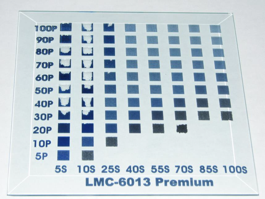
Next, design a varying power/speed grid. The goal is to make a series of markings on the piece that will vary from low heat to high heat. The grid should look something like the one shown in Figure A. In this grid, P denotes % Power and S denotes % Speed. Adjust your laser’s settings to match the selected colors, and then mark the substrate.
Evaluating the Marking Results
After you have marked the object, you should observe a variation of marks. They should range from barely visible to a slight destruction of the substrate, as seen in the photo in figure B. On this stainless steel tag you can see that marking starts at about 80% power and 100% speed. It can also be seen that at about 100% power and 2% speed the markings are starting to bleed and dimple the metal, these marks are overdone. Choose settings that give a durable mark without overpowering or damaging the object. In this example, settings around 100% power and 30-60% speed should be optimal.

If you are using a lower power laser, i.e. 25 or 30 watts, and are having trouble marking certain substrates, here is another tip. You can increase your Dots per Inch (DPI) and deliver more energy to the surface of the substrate. Most lasers have a default setting of 500 DPI, but can be increased to 1000 DPI or even greater, depending on the manufacturer or software. Increasing the DPI will put more heat into the same amount of area, which should help when marking on more difficult substrates.
Conclusions
Using this method when marking a substrate for the first time can save you time and money. A well designed marking test grid will allow you to very quickly decide the laser settings you will need to mark your part with CerMark products. You will only waste one piece of your substrate while easily finding the optimum settings for the marking you need to do.